How to do PCB design
2024-11-22

What is component packaging? //sznewmeto.com/
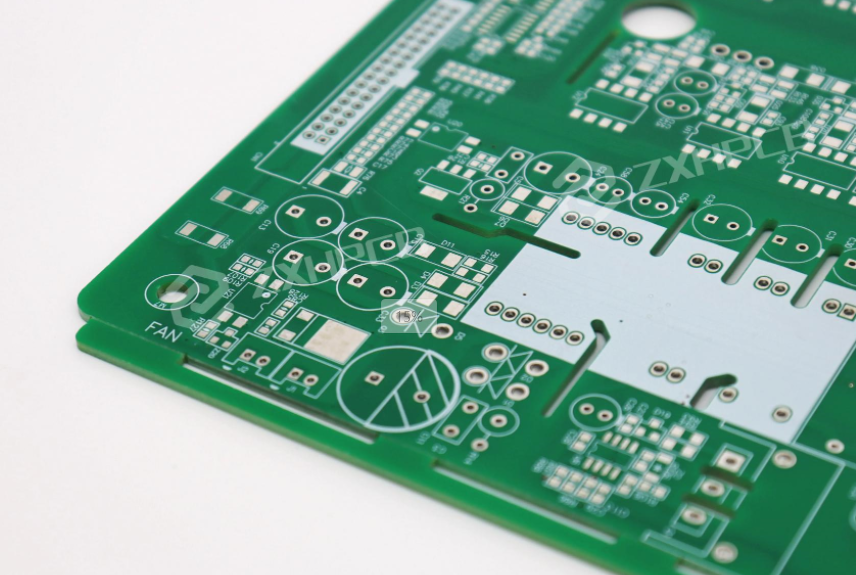
Component packaging, in simple terms, refers to both the packaging method of the component and the shape and size of the component's solder pads.
When drawing a PCB board, the first thing to ensure is that the component packaging is drawn correctly, otherwise the components may not be able to be soldered to the finished board.
Component packaging, in simple terms, refers to both the packaging method of the component and the shape and size of the component's solder pads.
When drawing a PCB board, the first thing to ensure is that the component packaging is drawn correctly, otherwise the components may not be able to be soldered to the finished board.
There are significant differences in the shape and size of various components produced by different factories, so there are also many different forms of component packaging.
Overall, current packaging is mainly divided into two categories. There are two types: direct insertion type and surface mount type. In addition, detailed classification can be further divided into the following categories:
Overall, current packaging is mainly divided into two categories. There are two types: direct insertion type and surface mount type. In addition, detailed classification can be further divided into the following categories:
SOP/SOI packaging: Small outline package

PLCC package: Plastic led chip charger Plastic J lead chip package

QFP package: Quid flat package with four side pins

BGA package: Ball grid array package Ball grid array package

CSP packaging: Chip scale package

SIP encapsulation: Single inline package

DIP package: Double inline package

What are resistors, capacitors, inductors, magnetic beads, diodes, and transistors?
For the types of components commonly used in PCB boards, further understanding may be needed.
(1) Resistors are relatively simple, and surface mount resistors are usually used.
(2) Capacitors are more complex, and commonly used types include ceramic capacitors, electrolytic capacitors, etc. Ceramic capacitors belong to non-polar capacitors, usually available in two types: X7R capacitors and Y5V capacitors, both of which are relatively small in size. Electrolytic capacitors are polarized capacitors, including aluminum electrolytic capacitors, tantalum electrolytic capacitors (tantalum capacitors), etc. Generally speaking, the capacitance of ceramic capacitors is relatively small, while the capacitance of electrolytic capacitors is larger. In addition, aluminum electrolytic capacitors are generally large in size and come in direct insertion packaging; And Tan capacitors are smaller in size and packaged in surface mount. In the schematic diagram, some capacitors have a+sign next to them, which represents polarized capacitors.
(3) The commonly used inductors are chip stacked inductors and chip power inductors. The volume of chip stacked inductors is very small, while the volume of chip power inductors is slightly larger, making them more suitable for high current and high inductance situations.
(4) Magnetic beads are actually single turn coils, also known as single turn inductors, with very small inductance. Specially designed to suppress high-frequency noise and spike interference on signal lines and power lines.
(5) The commonly used diodes are LED light diodes and Schottky diodes.
(6) The commonly used transistors include triodes and field-effect transistors (MOSFETs). A transistor is a current control component, divided into two types: PNP and NPN. The three poles are the base, emitter, and collector, respectively. MOS transistors are voltage controlled components, divided into two types: P-channel and N-channel. Another type is the enhancement type and the isolation type, with the three poles being the gate, source, and drain, respectively.
What do the numbers 0402 and 0603 represent?
These numbers refer to the packaging size of surface mount components such as resistors, capacitors, inductors, etc.
These numbers refer to the packaging size of surface mount components such as resistors, capacitors, inductors, etc.
The following figure shows the relationship between these packages and dimensions:

If you want to know more about pcb design, please click on the website and look forward to communicating more:
//sznewmeto.com/
BGA welding operation guide
Why is ICT testing rarely used in PCBA production
Related Article